Computer Language
When designing a product, defining its specifications is crucial. This principle applies to computer hardware and software as well. The Instruction Set Architecture (ISA) serves as the specification for a computer's software interface. To understand how a computer is built and operates, we need to grasp the instructions that drive it. In this section, we will explore the MIPS assembly language and how to map high-level programming concepts to low-level machine instructions.
Basic Concepts
Commands in high-level programming languages, such as C, Java, or Python, are called statements. These statements are mapped to instructions in assembly language. For example, the C statement p = x + y * z can be translated into MIPS assembly as a series of instructions like add $s0, $s1, $s2. Typically, a single high-level statement translates into multiple low-level instructions.
An instruction is a primitive operation that the CPU executes. The collection of instructions that a CPU can execute is known as its Instruction Set. CPUs are compatible if they use the same instruction set.
In low-level programming, data is stored in hardware, so understanding the fundamental hardware structure and the instruction set, which forms the ISA (Instruction Set Architecture), is essential.
MIPS Assembly Language
MIPS is a family of processors, including models like the MIPS R2000/R3000 (32-bit), MIPS R4000 (64-bit), and MIPS R8000 (for graphics or scientific applications). Here, we introduce the MIPS R2000 instruction set.
The amount of data that a CPU can process in a single instruction is called the word size. The MIPS R2000 has a word size of 32 bits, meaning it can process 32 bits of data in a single instruction.
Instruction sets are divided into two categories: RISC (Reduced Instruction Set Computer) and CISC (Complex Instruction Set Computer). MIPS is a RISC architecture, meaning it has a small number of simple instructions, making it faster to execute instructions. In contrast, CISC architectures have a large number of complex instructions, offering more functionality but potentially increasing the complexity for programmers.
🤔 Prior to the early 1980s, machines were built with more and more complex instruction sets. Why has there been a move to RISC machines away from complex instruction machines?
Answer: The move to RISC (Reduced Instruction Set Computer) architectures from complex instruction set computers (CISC) was driven by:
- Simplicity and Speed: RISC uses a small set of simple instructions, enabling faster execution.
- Efficient Pipelining: RISC designs facilitate pipelining, allowing multiple instructions to be processed simultaneously.
- Lower Cost and Power Consumption: Simpler designs reduce manufacturing costs and power usage.
- Compiler Optimization: Modern compilers efficiently translate high-level code into RISC instructions.
- Predictable Performance: Uniform instruction length and simple addressing modes in RISC lead to more consistent and optimized performance.
These advantages made RISC architectures more efficient, cost-effective, and easier to implement, driving the shift away from CISC architectures.
Sources:
Stored Program Concept (Von Neumann Machine)
Modern computers are built on two fundamental principles: instructions are represented as binary numbers, and programs must be loaded into memory before execution. This concept is known as the stored program concept or the Von Neumann Machine. This allows instruction sets to be distributed in binary form, enabling compatibility across various computers that share the same instruction set architecture.
Instructions Structure
We should understand hardware information:
- Memory: Data and instructions are stored in memory.
- Registers: Temporary storage locations in the CPU.
- Instruction Format: How instructions are structured.
- Addressing Mode: How to access data in memory.
Basic Computer Structure
A basic computer structure comprises the control unit, datapath, memory, and I/O devices. The control unit and datapath together form the processor. Registers are stored in the datapath of the processor. Data is loaded from memory into the registers, operations are performed, and the results are stored back into memory.

The Control Unit directs the operation of the processor, while the Datapath performs arithmetic and logic operations via the ALU (Arithmetic Logic Unit) and stores intermediate data in Registers. Memory holds the program, data, and instructions. I/O Devices manage input, output, and storage.
🗒️Cheat Sheet
CPU = Control Unit + Datapath = Control Unit + (ALU + Registers) Program in Memory = Data + Instructions I/O Devices = Input + Output + Storage
Memory
Memory is a large array of bytes, each with a unique address, making it byte addressable (starting from 0). In practice, most data is stored in words (4 bytes), and the address points to the first byte of the word, making it word addressable.
For example:
- Address
0x0000points to the first byte of the first word. - Address
0x0004points to the first byte of the second word.
If we use 32 bits to represent memory addresses, we can address up to (2^32) bytes of memory, which equals 4GB of memory.
In MIPS architecture, all byte addresses must be word-aligned, meaning the address must be a multiple of 4. This ensures that the CPU can access memory efficiently for each instruction.
Here is an illustration of byte and word addresses in memory:
| Address (Hex) | Byte 1 | Byte 2 | Byte 3 | Byte 4 |
|---|---|---|---|---|
| 0x0000 | 0x01 | 0x02 | 0x03 | 0x04 |
| 0x0004 | 0x05 | 0x06 | 0x07 | 0x08 |
| 0x0008 | 0x09 | 0x0A | 0x0B | 0x0C |
In this example:
- Address
0x0000,0x0004, and0x0008point to the first byte of each word and are word-aligned.
🗒️Cheat Sheet
- Byte Addressable: Each byte has a unique address.
- Word Addressable: Each address points to a word (4 bytes).
- Word-Aligned: Addresses must be multiples of 4 in MIPS.
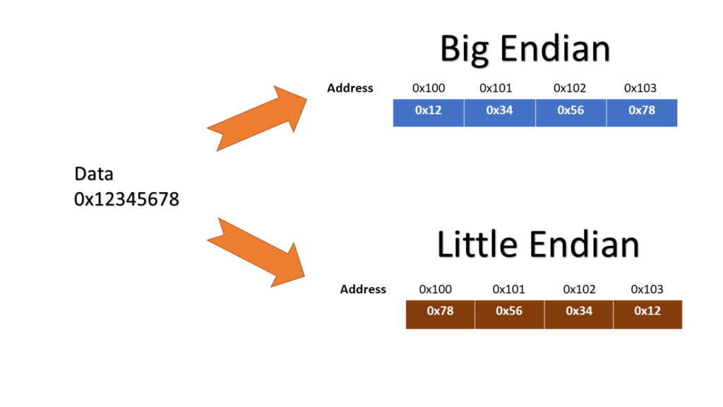
Byte-Order or Endianness
Endianness refers to the order in which bytes are stored in memory. There are two types of endianness:
- Big-Endian: The most significant byte (MSB) is stored at the lowest memory address. MIPS uses big-endian format.
- Little-Endian: The least significant byte (LSB) is stored at the lowest memory address.
Quick Quiz:
| a. | 0x12345678 |
|---|---|
| b. | 0xbeadf00d |
🤔 Show how the data in the table above would be arranged in memory of little endian and big endian machine. Assume the data is stored starting at address 0.
Answer:
- For 0x12345678
| Address | Big-Endian | Little-Endian |
|---|---|---|
| 0 | 12 | 78 |
| 1 | 34 | 56 |
| 2 | 56 | 34 |
| 3 | 78 | 12 |
- For 0xbeadf00d
| Address | Big-Endian | Little-Endian |
|---|---|---|
| 0 | be | 0d |
| 1 | ad | f0 |
| 2 | f0 | ad |
| 3 | 0d | be |
🤔 If a decimal number 1,000,000 (000F424016) is to be stored starting from address 80, consider using 1. Big-Endian 2. Little-Endian. What is the content of memory at that address?
Answer:
- Big-Endian
| Address | Content |
|---|---|
| 80 | 00 |
| 81 | 0F |
| 82 | 42 |
| 83 | 40 |
- Little-Endian
| Address | Content |
|---|---|
| 80 | 40 |
| 81 | 42 |
| 82 | 0F |
| 83 | 00 |
Registers
Registers are small, fast storage locations within the CPU that temporarily hold data such as operands, addresses, and results. Due to their limited number, registers offer quicker access than main memory (4 bytes per register). MIPS architecture features 32 general-purpose 32-bit registers and 32 floating-point registers (f1, ..., $f31). Additionally, it includes special-purpose registers like the Program Counter (PC), Stack Pointer (SP), and Return Address (RA).
Two 32-bit numbers can be multiplied into a 64-bit number. MIPS uses Hi and Lo special registers to store the high and low bits of the result, or the remainder and quotient of a division operation. For example, after a multiplication operation, the Hi register stores the upper 32 bits, while the Lo register stores the lower 32 bits.
| Operation | Hi Register | Lo Register |
|---|---|---|
| Multiplication | Upper 32 bits of result | Lower 32 bits of result |
| Division | Remainder | Quotient |
The Program Counter (PC) is a 32-bit special register that holds the address of the next instruction to be executed, automatically incrementing after each instruction is fetched.
Most programs use more variables than there are registers available. Therefore, compilers store the most frequently used variables in registers and keep the rest in memory, using load and store instructions to transfer data between memory and registers. Spilling registers involves moving data from registers to memory to free up registers for other variables.

- Coprocessor 0 (CP0): Handles exceptions, controls the MMU (Memory Management Unit), and manages the TLB (Translation Lookaside Buffer).
- Coprocessor 1 (CP1): Floating Point Unit (FPU), Handles floating-point operations.
🤔 Why not more registers?
Answer:
- Decoding Complexity: Accessing a large number of registers can slow down the decoding process, making the CPU clock cycle longer and reducing overall speed.
- Power Consumption: More registers consume more power, which can lead to higher energy consumption and heat generation.
General Purpose Registers (GPRs)
| Type | Name | Number | Usage |
|---|---|---|---|
| Assembler | $at | $1 | Assembler temporary, reserved for assembler |
| OS-related | $k0-$k1 | $26-$27 | Reserved for OS |
| OS-related | $v0-$v1 | $2-$3 | Values for results |
| Memory Management | $fp | $30 | Frame pointer |
| Memory Management | $sp | $29 | Stack pointer |
| Memory Management | $gp | $28 | Global pointer |
| Return Address | $ra | $31 | Return address for function calls |
| Procedure Call | $a0-$a3 | $4-$7 | Function arguments |
| More Temporaries | $t8-$t9 | $24-$25 | More temporary storage |
| Saved Temporaries | $s0-$s7 | $16-$23 | Saved temporary, preserved across calls |
| Temporary | $t0-$t7 | $8-$15 | Temporary storage, not preserved across calls |
| Variables/constants | $zero | $0 | Constant value 0, read-only |
🔍 Deep Dive: Usage of Registers
- $a0 - $a3 (Arguments): Used to pass arguments to functions during system calls.
- $ra (Return Address): Stores the return address for function calls.
- $gp (Global Pointer): Points to the first variable address in the static data segment in memory.
- $sp (Stack Pointer): Points to the top of the stack.
- $fp (Frame Pointer): Points to the bottom of the stack frame (activation record or procedure frame).
- $s0 - $s7 (Saved Temporaries): Stores frequently used variables, preserved across function calls.
- $t0 - $t9 (Temporaries): Temporary storage for arithmetic operations, not preserved across function calls.
- $zero (Zero): Constant value 0, read-only, hardwired to zero.
When initializing variables in high-level languages, the compiler creates a symbol table to map variables to registers and provides this to the OS before runtime.
Memory Management and Related Registers
A program in memory is divided into five address segments (from high to low addresses):
- Stack: Contains local variables, function arguments, and return addresses. Grows from high to low addresses.
- Heap: Used for dynamically allocated memory, like pointers. Grows from low to high addresses.
- Static Data: Stores global variables that do not change during program execution.
- Text (or Code): Contains the program instructions.
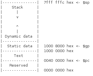
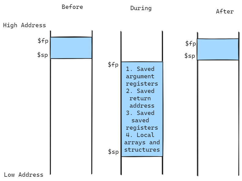
Procedure Frame (Activation Record): Each function call creates a new frame on the stack, storing the return address, arguments, local variables, and saved registers. The frame pointer ($fp) points to the base of the current frame, while the stack pointer ($sp) points to the top of the stack.
- Global Pointer ($gp): Points to the first variable address in the static data segment.
- Stack Pointer ($sp): Points to the top of the stack.
- Frame Pointer ($fp): Points to the base of the current procedure frame.
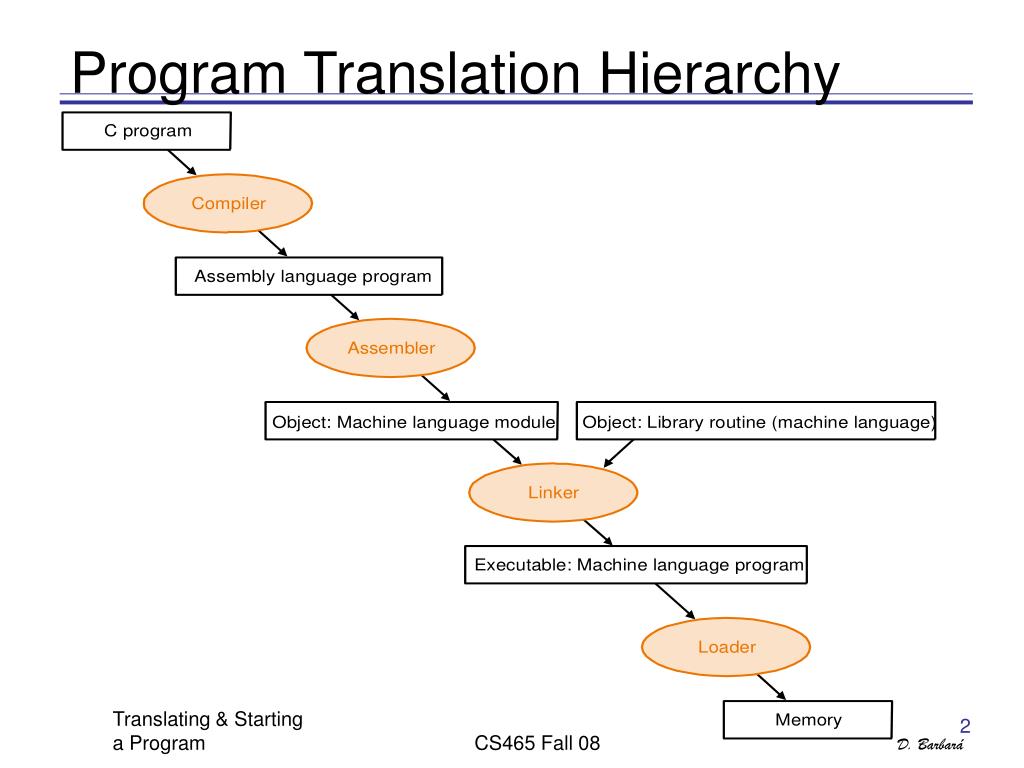
Translation and Execution of Programs
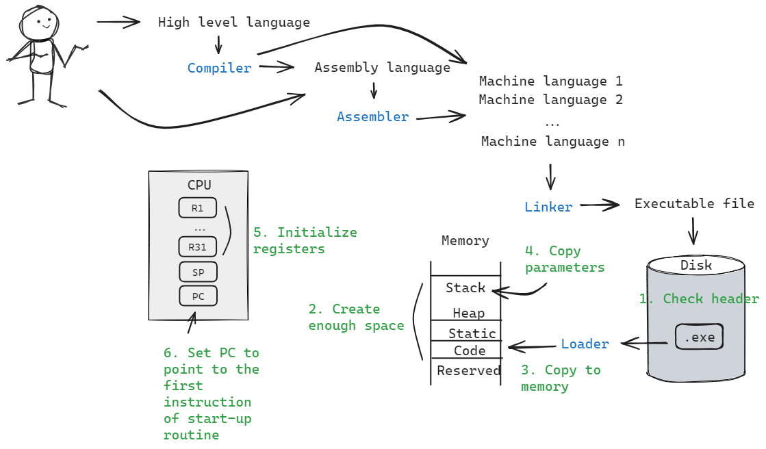
Computer hardware is designed to execute machine code, a sequence of binary instructions. High-level languages like C, Java, or Python are translated into machine code to be executed by the CPU. This translation process involves several steps, including compilation, assembly, linking, and loading.
Steps
High-level languages are translated into machine code through a series of steps:
- High-Level Language (e.g., C, Java) Program -> Compiler -> Assembly Language Program: The source code is converted into assembly language.
- Assembly Language Program -> Assembler -> Object Code: The assembly code is translated into machine code, also known as object code.
- Object Code -> Linker -> Executable Code: The linker combines object code with required libraries and resolves address references to produce an executable file.
- Executable Code -> Loader -> Memory -> Execution: The loader loads the executable code into memory, preparing it for execution by the CPU.
Example:
Imagine you wrote a C program that adds two numbers. The compiler translates the C code into assembly language. The assembler converts this assembly language into object code. The linker combines this object code with necessary libraries (like printf) and resolves address references to produce the final executable. The loader then loads this executable into memory, where it can be executed by the CPU.
In some systems, these steps are optimized for speed. For instance, some systems produce pre-linked modules, or use a linking loader to combine linking and loading steps.
Program Translation and Execution
| Step | Description |
|---|---|
| Compiler | Converts high-level language (C, Java) into assembly language. |
| Assembler | Translates assembly language into object code (machine code). |
| Linker | Combines object code with libraries and resolves address references to create executable code. |
| Loader | Loads executable code into memory for execution by the CPU. |
🔍 Deep dive: File extensions
UNIX:
.cfor C source code.sfor assembly code.ofor object code.afor static libraries.sofor dynamic libraries.outfor executables (default output for theldlinker)
MS-DOS:
.cfor C source code.asmfor assembly code.objfor object code.exefor executables.libfor static libraries.dllfor dynamic libraries
Loader
- Read Executable Header: Determine the size of the text and data segments.
- Allocate Memory: Allocate a large enough contiguous block of memory.
- Copy Instructions and Data: Transfer executable instructions and data into memory.
- Copy Arguments: Place program arguments into the stack.
- Initialize Registers: Set up registers, with the stack pointer set to the available address.
- Jump to Start-Up Routine: Transfer control to the start-up routine, which copies arguments from the stack to argument registers and then jumps to the main program. After the main program finishes, control returns to the start-up routine, which calls the exit system call.
All programs run as OS subroutines, ensuring system security by maintaining OS control.
Assembler Components
After reviewing the sources, here is the revised information on the components of an assembler:
- Header: Contains metadata about the file, such as size and the location of various segments.
- Text Segment: Contains the actual machine code instructions.
- Static Data Segment: Holds global variables, constants, and static data.
- Relocation Information: Identifies addresses that need to be updated when the program is loaded into memory.
- Symbol Table: Stores information about symbols (labels and variables), including addresses for external references and unresolved references.
- Debugging Information: Includes line number mappings and other data useful for debugging, linking the machine code back to the source code.
Java Program Translation
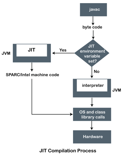
Here is an improved explanation of the Java program translation process with a diagram:
- Source Code Compilation: The Java source code (
.javafiles) is compiled into bytecode (.classfiles) by the Java compiler. These bytecode files are platform-independent and contain address references. - Loading and Linking: When a Java program is run, the Java Virtual Machine (JVM) loads the necessary
.classfiles and links them. The JVM resolves the references to libraries and other classes as needed during this process. - Just-In-Time (JIT) Compilation: For improved performance, the JVM uses a Just-In-Time (JIT) compiler. The JIT compiler identifies "hot" methods that are frequently executed and compiles them into native machine code. This native code is then cached for future use, which reduces the overhead of interpretation.
🤔 What is the advantage of an interpreter over a translator when designing Java?
Answer:
In C, the code is directly compiled into machine-specific code, making it non-portable across different platforms. The C program undergoes this sequence: C program -> Compiler -> Machine code -> Machine (Compilation or Translation).
In Java, the code is first compiled into platform-independent bytecode, which can then be executed on any machine with a Java Virtual Machine (JVM). This process is: Java program -> Compiler -> Java bytecode -> JVM + JIT -> Machine (Interpretation).
The key advantage of this approach is portability. Java bytecode can run on any platform with a JVM, making Java applications platform-independent. Additionally, the JVM can optimize the code at runtime using Just-In-Time (JIT) compilation, enhancing performance.
The table provided for the arithmetic instructions is mostly correct, but there are a few inaccuracies and clarifications needed. Here is a revised version of the table:
Arithmetic Instructions
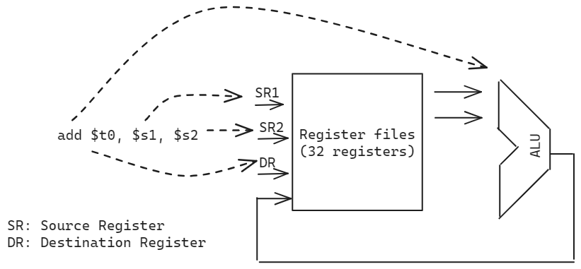
Perform binary operations. All instructions follow the format op dest, src1, src2, where op is the operation, dest is the destination register, and src1 and src2 are the source registers. Immediate and unsigned operations have similar formats with slight variations.
| Operation | Format | Function | Example (C to MIPS) |
|---|---|---|---|
| Addition | add $d, $s, $t | $d <- $s + $t | p = x + y -> add $s0, $s1, $s2 |
| Subtraction | sub $d, $s, $t | $d <- $s - $t | p = x - y -> sub $s0, $s1, $s2 |
| Addition Immediate | addi $d, $s, imm | $d <- $s + imm | p = x + 5 -> addi $s0, $s1, 5 |
| Unsigned Addition | addu $d, $s, $t | $d <- $s + $t (unsigned) | p = x + y -> addu $s0, $s1, $s2 |
| Unsigned Subtraction | subu $d, $s, $t | $d <- $s - $t (unsigned) | p = x - y -> subu $s0, $s1, $s2 |
| Unsigned Addition Immediate | addiu $d, $s, imm | $d <- $s + imm (unsigned) | p = x + 5 -> addiu $s0, $s1, 5 |
| Multiplication | mult $s, $t | Lo, Hi <- $s * $t | mult $s1, $s2 (x * y -> Lo, Hi) |
| Multiplication with Overflow | mul $d, $s, $t | $d <- $s * $t (with overflow check) | mul $s0, $s1, $s2 (x * y -> $s0) |
| Division | div $s, $t | Lo <- $s / $t, Hi <- $s % $t | div $s1, $s2 (x / y -> Lo, x % y -> Hi) |
Example:
- C code:
a = b + c + d; e = f - a; - MIPS assembly:
add $t0, $s1, $s2(b + c -> $t0)add $t0, $t0, $s3(b + c + d -> $t0)sub $s4, $s5, $t0(f - (b + c + d) -> $s4)
Steps in Arithmetic Instruction Execution:
- Register Assignment: The compiler assigns registers to variables.
- Translation: Convert high-level language statements to assembly instructions.
- Optimization: The compiler optimizes the instructions for performance.
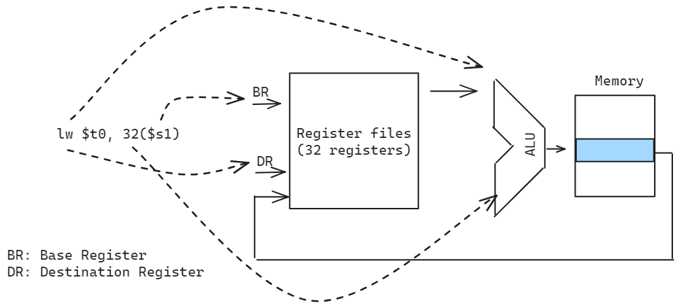
Data Transfer Instructions
Move data between memory and registers. The format is op dest, src, where op is the operation, dest is the destination register, and src is the source register or memory address.
| Operation | Format | Function | Example (C to MIPS) |
|---|---|---|---|
| Load Word | lw $t, offset($s) | $t <- Mem[$s + offset] | p = A[i] -> lw $s0, i($s1) |
| Store Word | sw $t, offset($s) | Mem[$s + offset] <- $t | A[i] = p -> sw $s0, i($s1) |
| Load Immediate | li $t, imm | $t <- imm | p = 5 -> li $s0, 5 |
| Load Address | la $t, label | $t <- &label | p = &A -> la $s0, A |
| Move | move $d, $s | $d <- $s | p = q -> move $s0, $s1 |
| Load Byte | lb $t, offset($s) | $t <- Mem[$s + offset] (byte) | p = A[i] -> lb $s0, i($s1) |
| Store Byte | sb $t, offset($s) | Mem[$s + offset] <- $t (byte) | A[i] = p -> sb $s0, i($s1) |
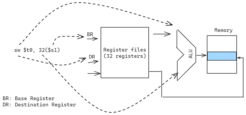
Example:
- C code:
A[12] = h + A[8];(s2 holds h) - MIPS assembly:
lw $t0, 32($s1)(Load A[8] -> $t0)add $t0, $s2, $t0(h + A[8] -> $t0)sw $t0, 48($s1)(Store h + A[8] -> A[12])
Flow Control Instructions
Control the flow of execution based on conditions. The format is op src1, src2, label, where op is the operation, src1 and src2 are source registers, and label is the target label.
| Operation | Format | Function | Example (C to MIPS) |
|---|---|---|---|
| Branch Equal | beq $s, $t, label | Branch to label if $s = $t | if (x == y) goto L -> beq $s0, $s1, L |
| Branch Not Equal | bne $s, $t, label | Branch to label if $s != $t | if (x != y) goto L -> bne $s0, $s1, L |
| Jump | j label | Jump to label | goto L -> j L |
Example - If-Else Statement:
- C code:
if (x == y) z = 1; else z = 0; - MIPS assembly:
beq $s0, $s1, L1(Branch to L1 if x == y)li $s2, 0(z = 0)j L2(Jump to L2)L1: li $s2, 1(z = 1)L2: ...
Example - Loop:
- C code:
for (i = 0; i < 10; i++) sum += A[i]; - MIPS assembly:
li $s0, 0(i = 0)li $s1, 10(Upper bound)li $s2, 0(sum = 0)Loop: beq $s0, $s1, Exit(Check loop condition)lw $t0, 4($s0)(Load A[i] -> $t0)add $s2, $s2, $t0(sum += A[i])addi $s0, $s0, 1(Increment i)j Loop(Jump back to Loop)Exit: ...
Basic Blocks
A basic block is a sequence of instructions with a single entry point and a single exit point, containing no branches except at the end, and no branch targets except at the beginning. When the compiler translates high-level code to assembly, it identifies basic blocks to optimize execution block by block.
MIPS does not provide blt, bgt, ble, and bge instructions. Instead, these comparisons are achieved by combining beq, bne, and slt (Set on Less Than) instructions to produce Pseudo-Instructions or Directive Instructions. Here is the mapping:
| High-Level Comparison | MIPS Pseudo-Instruction | Equivalent MIPS Instructions |
|---|---|---|
if (x < y) | blt $s0, $s1, label | slt $t0, $s0, $s1 bne $t0, $zero, label |
if (x > y) | bgt $s0, $s1, label | slt $t0, $s1, $s0 bne $t0, $zero, label |
if (x <= y) | ble $s0, $s1, label | slt $t0, $s1, $s0 beq $t0, $zero, label |
if (x >= y) | bge $s0, $s1, label | slt $t0, $s0, $s1 beq $t0, $zero, label |
Explanation:
slt $t0, $s0, $s1: Sets$t0to 1 if$s0 < $s1, otherwise sets$t0to 0.bne $t0, $zero, label: Branches tolabelif$t0is not equal to 0.beq $t0, $zero, label: Branches tolabelif$t0is equal to 0.
🔍 Deep Dive: Pseudo-Instructions
Pseudo-Instructions in MIPS MIPS does not provide some instructions directly, so we use pseudo-instructions to achieve the desired functionality. Here are some common pseudo-instructions and their equivalents in MIPS assembly:
| Pseudo-instruction | What it Accomplishes | Solution |
|---|---|---|
move $t1, $t2 | t2 | add $t1, $t2, $zero |
clear $t0 | $t0 = 0 | add $t0, $zero, $zero |
beq $t1, small, L | if ($t1 == small) go to L | addi $at, $zero, small beq $t1, $at, L |
beq $t2, big, L | if ($t2 == big) go to L | lui $at, upper(big) ori $at, $at, lower(big) beq $t2, $at, L |
li $t1, small | $t1 = small | addi $t1, $zero, small |
li $t2, big | $t2 = big | lui $t2, upper(big) ori $t2, $t2, lower(big) |
addi $t5, big | t2 + big | lui $at, upper(big) ori $at, $at, lower(big) add $t5, $t2, $at |
lw $t5, big($t2) | t2 + big] | lui $at, upper(big) ori $at, $at, lower(big) add $at, $t2, $at lw $t5, 0($at) |
Conditional Branching with Pseudo-Instructions
MIPS lacks specific conditional instructions like ble, bgt, blt, and bge, so we use pseudo-instructions:
| Pseudo-instruction | What it Accomplishes | Solution |
|---|---|---|
ble $t3, $t5, L | if ($t3 <= $t5) go to L | slt $at, $t5, $t3 beq $at, $zero, L |
bgt $t4, $t5, L | if ($t4 > $t5) go to L | slt $at, $t5, $t4 bne $at, $zero, L |
bge $t5, $t3, L | if ($t5 >= $t3) go to L | slt $at, $t3, $t5 beq $at, $zero, L |
Addressing Immediate Values
The terms small and big refer to the size of the immediate value:
-
Small: Fits within 16 bits, can be used directly.
-
Big: Requires more than 16 bits, split into upper and lower parts using
luiandori. -
Example:
- Small immediate:
addi $t1, $zero, 15 - Big immediate:
lui $t2, 0x1234followed byori $t2, $t2, 0x5678(to load 0x12345678 into $t2).
- Small immediate:
Logical Instructions
Shift instructions move bits left or right by a specified number of positions. The format is op dest, src, count, where op is the operation, dest is the destination register, src is the source register, and count is the number of positions to shift.
| Operation | Format | Function | Example (C to MIPS) |
|---|---|---|---|
| Shift Left Logical | sll $d, $t, shamt | $d <- $t << shamt | p = q << 2 -> sll $s0, $s1, 2 |
| Shift Right Logical | srl $d, $t, shamt | $d <- $t >> shamt | p = q >> 3 -> srl $s0, $s1, 3 |
| Shift Right Arithmetic | sra $d, $t, shamt | $d <- $t >> shamt (sign-extended) | p = q >> 3 -> sra $s0, $s1, 3 |
- shamt: Shift amount, the number of positions to shift.
- Shift Right Arithmetic (sra) preserves the sign bit during right shifts. For example,
1101 >> 1becomes1110. - Every shift operation is like multiplying or dividing by 2. For example,
x << 2is equivalent tox * 4.
Note: SLA (Shift Left Arithmetic) is equal to SLL (Shift Left Logical) in MIPS, hence it is not a separate MIPS instruction.
AND, OR, NOR, and XOR instructions perform bitwise logical operations. The format is op dest, src1, src2, where op is the operation, dest is the destination register, and src1 and src2 are the source registers.
| Operation | Format | Function | Example (C to MIPS) |
|---|---|---|---|
| AND | and $d, $s, $t | $d <- $s & $t | p = q & r -> and $s0, $s1, $s2 |
| OR | or $d, $s, $t | $d <- $s | $t | p = q | r -> or $s0, $s1, $s2 |
| NOR | nor $d, $s, $t | $d <- ~($s | $t) | p = ~(q | r) -> nor $s0, $s1, $s2 |
| XOR | xor $d, $s, $t | $d <- $s ^ $t | p = q ^ r -> xor $s0, $s1, $s2 |
- XOR (Exclusive OR): Sets the destination bit to 1 if only one of the source bits is 1.
Bitwise Operations:
- AND:
0011 & 1010 = 0010-> Mask bits in a word, i.e., select some bits, clear others to 0. - OR:
0011 | 1010 = 1011-> Include bits in a word, i.e., set some bits to 1, leave others unchanged. - NOR:
~(0011 | 1010) = 0100-> Negate the OR operation, i.e., set bits to 1 where both inputs are 0. - XOR:
0011 ^ 1010 = 1001-> Exclusive OR, i.e., set bits to 1 where only one input bit is 1.
Pseudo-Instructions (MIPS does not have direct instructions for these operations):
not $d, $s: Equivalent tonor $d, $s, $zeroornor $d, $s, $s(logical NOT operation) ->not $s0, $s1
Example
- C code:
p = (q & r) | (s << 2);($s1holds q,$s2holds r,$s3holds s) - MIPS assembly:
and $t0, $s1, $s2(q & r -> $t0)sll $t1, $s3, 2(s << 2 -> $t1)or $s0, $t0, $t1((q & r) | (s << 2) -> $s0)
Quick Quiz:
- a.
andn $t1, $s2, $s3(ANDN: Set to 1 if$s2AND NOT$s3) - b.
xnor $t1, $s2, $s3(XNOR: Set to 1 if both are equal or NOT XOR)
🤔 How can we implement the above operations using the minimal set of MIPS instructions? If $s2 = 0x00FFA5A5 and s3 = 0xFFFF003C, what is the result of t1?
$s2 = 0x00FFA5A5 and s3 = 0xFFFF003C, what is the result of t1?$s2= 0x00FFA5A5 = 0000 0000 1111 1111 1010 0101 1010 0101$s3= 0xFFFF003C = 1111 1111 1111 1111 0000 0000 0011 1100
a.
nor $t1, $s3, $zero  # NOT $s3
and $t1, $s2, $t1    # $s2 AND NOT $s3
$t1 = 0x0000A581
b.
xor $t1, $s2, $s3    # $s2 XOR $s3
nor $t1, $t1, $zero  # NOT ($s2 XOR $s3)
$t1 = 0x00FF5A66
Quick Quiz:
- a.
A = B & C[0]; - b.
A = A ? B : C[0];
🤔 Consider the above two C statements, if the memory location at C[0] contians the integer value 0x00001234, and initial integer value of A and B are 0x00000000 and 0x00002222, what is the result value of A?
Assume t2 = B, $s1 = base address of C.
$t1= 0x00000000 = 0000 0000 0000 0000 0000 0000 0000 0000$t2= 0x00002222 = 0000 0000 0000 0000 0010 0010 0010 0010$s1= 0x00001234 = 0000 0000 0000 0000 0001 0010 0011 0100
a.
lw $t0, 0($s1)  # Load C[0] into $t0
and $t1, $t2, $t0  # B & C[0] -> A
$t1 = 0x00000220 = 0000 0000 0000 0000 0000 0010 0010 0000
b.
beq $t1, $zero, Else  # If A == 0, go to Else
add $t1, $zero, $t2  # A = B
beq $zero, $zero, End  # Skip Else
Else: lw $t1, 0($s1)  # Load C[0] into $t0
End:
$t1 = 0x00001234 = 0000 0000 0000 0000 0001 0010 0011 0100
🤔 Implement this instruction: swap $s0, $1 with only 3 instructions and 2 registers.
swap $s0, $1 with only 3 instructions and 2 registers.xor $s0, $s0, $s1 # $s0 <- $s0 XOR $s1
xor $s1, $s0, $s1 # $s1 <- ($s0 XOR $s1) XOR $s1 = $s0
xor $s0, $s0, $s1 # $s0 <- ($s0 XOR $s1) XOR [($s0 XOR $s1) XOR $s1] = $s1Constants
To add a constant loaded from memory to a register, use the lw instruction to load the constant into a register. For example, to add a constant 4 to register $s3:
.data
AddConstant4: .word 4 # Define the constant 4 in memory

.text
main:
    lw $t0, AddConstant4 # Load the constant 4 from memory into $t0
    add $s3, $s3, $t0    # Add the value in $t0 to $s3
This approach requires a memory access, which can be slow. To optimize, use immediate instructions to load constants directly into registers without memory access:
addi $s3, $s3, 4 # Add the constant 4 to $s3Immediate instructions use a 16-bit immediate value, which is extended to 32 bits. The immediate value can be positive or negative with a range of to .
- For logical instructions like
andi, the immediate value is zero-extended. - For arithmetic instructions like
addi, the immediate value is sign-extended, where positive values are padded with zeros and negative values are padded with ones.
MIPS provides lui (Load Upper Immediate) to load the upper 16 bits of a 32-bit constant into a register. For example, to load the constant 0x1234 into register $t0:
lui $t0, 0x1234 # Load the upper 16 bits of 0x1234 into $t0To load the constant 0x12345678 into register $t0, you need two instructions, where ori (OR Immediate) loads the lower 16 bits:
lui $t0, 0x1234       # Load upper 16 bits
ori $t0, $t0, 0x5678  # Load lower 16 bits
🤔 Load the following 32-bit constant into register $s0: 0000 0000 0011 1101 0000 1001 0000 0000
$s0: 0000 0000 0011 1101 0000 1001 0000 0000lui $s0, 0x003D # Load the upper 16 bits: 0000 0000 0011 1101
ori $s0, $s0, 0x0900 # Load the lower 16 bits: 0000 1001 0000 0000Quick Quiz:
- a.
$t0= 0x55555555,$t1= 0x12345678 - b.
$t0= 0xBEADFEED,$t1= 0xDEADFADE
- What is the value of
$t2after the following instructions?
sll $t2, $t0, 4
or $t2, $t2, $t1- What is the value of
$t3after the following instructions?
sll $t2, $t0, 4
andi $t3, $t2, -1 # -1 = 0xFFFFFFFF
🤔 What are the results of the above operations?
Answer:
-
Value of
$t2:- a. 0x57755778
- b. 0xFEFFFEDE
-
Value of
$t3:- a. 0x00005550
- b. 0x0000EED0
Note: The immediate value can be negative! The range of immediate values is -2^15 to 2^15-1.
Assembly and Machine Code
In MIPS assembly, there are three types of instruction formats: R-type, I-type, and J-type.
| Instruction Type | Elements | Example Instructions |
|---|---|---|
| R-type | Three registers | add, sub, and, or, slt, sll, srl, sra |
| I-type | Two registers and one 16-bit constant/address | addi, lw, sw, beq, bne, andi, ori |
| J-type | One 26-bit address | j, jal |
Instruction Formats
- R-type:
op rs rt rd shamt funct - I-type:
op rs rt address/immediate - J-type:
op 26-bit address
A Field is a part of a continuous sequence of bits in a machine instruction that represents a register, immediate value, or address.
| Field | Length | Description |
|---|---|---|
op | 6 bits | Opcode, basic operation of the instruction |
rs | 5 bits | Source register |
rt | 5 bits | Target register |
rd | 5 bits | Destination register |
shamt | 5 bits | Shift amount for shift instructions |
funct | 6 bits | Function code, specifies the exact operation for R-type instructions like add, sub, etc. |
address/immediate | 16 bits | Memory address or immediate value (constant) |
address | 26 bits | Jump target address for J-type instructions |
See: Opcode (opens in a new tab)
Steps to Translate Instructions to Machine Code:
- Determine the instruction format (R-type, I-type, or J-type).
- Draw the corresponding machine instruction format.
- Look up the table for opcode, funct code, and register numbers.
Opcode vs. Funct:
- Opcode: Specifies the operation type (e.g., arithmetic, logical, memory access).
- Funct: Specifies the exact operation within the opcode category (e.g.,
add,sub,and,or).
OPCode Table
| 31-29 | 0(000) | 1(001) | 2(010) | 3(011) | 4(100) | 5(101) | 6(110) | 7(111) |
|---|---|---|---|---|---|---|---|---|
| 0(000) | R-format | bltz/gez | jump | jump & link | branch eq | branch ne | blez | bgtz |
| 1(001) | add immediate | addiu | set less than imm. | sltiu | andi | ori | xori | load upper imm. |
| 2(010) | TLB | flpt | ||||||
| 3(011) | ||||||||
| 4(100) | load byte | lh | lwl | load word | lbu | lhu | lwr | |
| 5(101) | store byte | sh | swl | store word | swr | |||
| 6(110) | lwc0 | lwc1 | ||||||
| 7(111) | swc0 | swc1 |
Function Code Table
| 5-3 | 0(000) | 1(001) | 2(010) | 3(011) | 4(100) | 5(101) | 6(110) | 7(111) |
|---|---|---|---|---|---|---|---|---|
| 0(000) | sll | srl | sra | sllv | syscall | break | ||
| 1(001) | jump reg. | jalr | ||||||
| 2(010) | mfhi | mthi | mflo | mtlo | ||||
| 3(011) | mult | multu | div | divu | ||||
| 4(100) | add | addu | subtract | subu | and | or | xor | nor |
| 5(101) | set l.t. | sltu | ||||||
| 6(110) | ||||||||
| 7(111) |
Register Table
| Name | Number | Usage |
|---|---|---|
$zero | 0 | Constant value 0 |
$at | 1 | Assembler temporary for Pseudoinstructions |
$v0-$v1 | 2-3 | Values for results and expression evaluation |
$a0-$a3 | 4-7 | Arguments to functions |
$t0-$t7 | 8-15 | Temporary data, not preserved across function calls |
$s0-$s7 | 16-23 | Saved temporary data, preserved across function calls |
$t8-$t9 | 24-25 | More temporary data, not preserved across function calls |
$k0-$k1 | 26-27 | Reserved for kernel, do not use |
$gp | 28 | Global pointer for data access |
$sp | 29 | Stack pointer |
$fp | 30 | Frame pointer |
$ra | 31 | Return address |
Example:
For the add instruction:
- R-type:
add $t1, $t2, $t3op= 000000 (All R-type instructions use a 000000 opcode)rs=$t2= 01010rt=$t3= 01011rd=$t1= 01001shamt= 00000 (not used)funct= 100000 (add)
The machine code for add $t1, $t2, $t3 is:
000000 01010 01011 01001 00000 100000Machine Language refers to instructions in numerical format that a computer's CPU can execute directly. A sequence of these instructions is called Machine Code.
In MIPS assembly, the order of register fields in machine code is different from the assembly code. In assembly, the format is op rd rs rt, while in machine code, the format is op rs rt rd.
Jump and Branch Addressing
MIPS differentiates between jump and branch instructions based on their address fields:
- Jump instructions use a 26-bit address field.
- Branch instructions use a 16-bit address field and employ PC-relative addressing, where the address is relative to the program counter (PC). The PC holds the address of the current instruction, allowing the CPU to branch within the range (-2^15) to (2^15-1) words or (-2^17) to (2^17-1) bytes from the current instruction, which is (131072) in decimal and (0x20000) in hexadecimal.
Example
Assembly Code:
Loop:
    sll $t1, $s3, 2
    add $t1, $t1, $s6
    lw $t0, 0($t1)
    bne $t0, $s5, Exit
    addi $s3, $s3, 1
    j Loop
Exit:
Machine Code (Decimal):
80000: 0 0 19 9 2 0    # sll $t1, $s3, 2
80004: 0 9 22 9 0 32   # add $t1, $t1, $s6
80008: 35 9 8 0        # lw $t0, 0($t1)
80012: 5 8 21 2        # bne $t0, $s5, Exit
80016: 8 19 19 1       # addi $s3, $s3, 1
80020: 2 20000         # j Loop
80024: ...
Assuming the loop starts at memory location 80000 in decimal.
To relatively address the Loop and Exit labels in branch instructions, we need to calculate the offset from the current instruction. Positive values are forward, and negative values are backward. In this example, when the branch condition is met, the program jumps to Exit, which is 2 instructions ahead (in machine code) from the current instruction. Hence, the 16-bit address field in the bne instruction is +2.
For addressing in the j instruction, the 26-bit address field is sufficient. MIPS systems have 2^32 bytes of memory (4GB) divided into 16 blocks of 256MB each. All programs should reside within a block. For instructions in the same block, the first 4 bits of the address remain the same. As all instructions are 4 bytes aligned, the last 2 bits of the address are always 0. Thus, the 26-bit (32 - 4 - 2) address field is enough to address instructions within the same block.
For instance, (80000)10 in 32-bit binary is (0000 0000 0000 0001 0011 1000 0100 0000)2. Removing the last 2 bits and the first 4 bits, we get (0000 0000 0000 0100 1110 0010 00)2 = (20000)10.
Long Distance Branch Addressing
In MIPS, branch instructions like beq and bne use PC-relative addressing, allowing them to jump within a range of (-2^15) to (2^15-1) words from the current instruction. This range is generally sufficient, but if the branch target is outside this range, the assembler handles it by transforming the branch into a combination of an inverted branch followed by a jump instruction.
Example:
beq $s0, $s1, LabelIf Label is too far for the beq instruction to reach, the assembler converts it to:
bne $s0, $s1, Next
j Label
Next:
Explanation:
bne $s0, $s1, Next: This instruction branches toNextif$s0is not equal to$s1, effectively inverting the original branch condition.j Label: If$s0equals$s1, thebeqcondition is satisfied, so the program continues to thisjinstruction, which can reach the distantLabel.Next:: The point to continue execution if the branch was not taken.
Reassembly
Steps to Translate Machine Code back to Assembly:
- Identify the instruction format by looking at the first 6 bits (opcode).
- Split the instruction into fields based on the format.
- Look up the opcode, funct code, and register numbers in the table.
Example:
- Bits:
0000 0000 1010 1111 1000 0000 0010 0000 - Opcode:
000000(R-type) rs:00101,rt:01111,rd:10000,shamt:00000,funct:100000add $s0, $a1, $t7
Quick Quiz: a. Op=0, rs=1, rt=2, rd=3, shamt=0, funct=32 b. Op =0x2B, rs=0x10, rt=0x5, const=0x4
🤔 What are the corresponding MIPS assembly instructions, type, and binary representation?
a.
- MIPS Assembly Instruction:
add $v1, $at, $v0 - Type: R-type
- Binary Representation:
000000 00001 00010 00011 00000 10 0000 - Hexadecimal Representation:
0x00221820
b.
- MIPS Assembly Instruction:
sw $a1, 4($s0) - Type: I-type
- Binary Representation:
101011 10000 01010 0000000000000100 - Hexadecimal Representation:
0xAE050004
🤔 How could modifying the MIPS processor and instruction format affect program size?
Question: We are considering modifying the MIPS processor, which involves changing the instruction format. Specifically, we propose reducing the number of registers to 8 and limiting the immediate field to 10 bits.
- What would be the new sizes for the bit fields in R-type and I-type instructions?
- How could these changes potentially decrease the size of a MIPS assembly program?
- How could these changes potentially increase the size of a MIPS assembly program?
Answer:
-
New Bit Field Sizes:
- R-type Instructions:
- opcode: 6 bits
- rs, rt, rd: 3 bits each
- shamt: 5 bits
- funct: 6 bits
- Total: 26 bits
- I-type Instructions:
- opcode: 6 bits
- rs, rt: 3 bits each
- immediate: 10 bits
- Total: 22 bits
- R-type Instructions:
-
Decrease in Program Size: The program size could decrease because each instruction now requires fewer bits (26 bits for R-type and 22 bits for I-type compared to the original 32 bits). This reduction means the program would take up less memory.
-
Increase in Program Size: The program size could increase because having fewer registers (8 instead of 32) and a smaller immediate field (10 bits instead of 16) might limit the program's flexibility. This limitation could require more instructions to achieve the same tasks, potentially leading to an overall increase in the number of instructions and thus a larger program size.
🤔 How can an assembler handle problems with PC-relative addressing in a branch instruction?
Question: Given your understanding of PC-relative addressing, explain why an assembler might have problems directly implementing the branch instruction in the following code sequence:
here: beq $s0, $s2, there
     ...
there: add $s0, $s0, $s0
Show how the assembler might rewrite this code sequence to solve these problems.
Answer:
The assembler might have problems because PC-relative addressing for the beq instruction requires the target address (there) to be within a certain range of the current instruction (here). If there is too far away, the immediate field cannot represent the offset.
To solve this problem, the assembler can use an unconditional jump (j) combined with a conditional branch to an intermediate label:
here: bne $s0, $s2, skip
      j there
skip: ...
there: add $s0, $s0, $s0
By introducing the skip label, the assembler can handle cases where the branch target is out of range for PC-relative addressing.
🤔 Suppose the program counter (PC) is at address 0x20000000. Is it possible to use jump or branch instructions to reach the address 0x20001400? Explain why or why not.
Answer:
Jump Instruction:
Yes, it is possible to use a jump (j) instruction to reach the address 0x20001400 from 0x20000000. The jump instruction in MIPS can jump to any address within the current 256MB region. The address range that can be reached by the jump instruction is determined by the 26-bit address field in the instruction, which is shifted left by 2 bits and combined with the upper 4 bits of the current PC. Given the current PC is 0x20000000, the range of addresses that can be jumped to is 0x20000000 to 0x2003FFFF. The target address 0x20001400 falls within this range.
Branch Instruction:
Yes, it is also possible to use a branch instruction such as beq (branch on equal) to reach the address 0x20001400 from 0x20000000, but only if the offset is within the allowable range. The branch instructions use a 16-bit signed offset, which allows branching within -2^15 to 2^15 - 1 instructions. Since each instruction is 4 bytes, this translates to a byte offset range of -131072 to 131068.
-
Calculate the Offset: .
-
Check the Offset Range: The offset 1280 instructions is within the range of
-32768to32767instructions, which is the range for a 16-bit signed offset.
Therefore, both the jump and branch instructions can be used to reach the address 0x20001400 from 0x20000000. The jump instruction can directly target the address, while the branch instruction can reach it if the offset falls within the specified range.
Tips1: Actually, we can check if the offset is within 0x20000 (131072) bytes, which is the range of the branch instruction, directly to see if it is possible to reach the target address without calculating like above.
Tips2: We know that jump instruction can reach any address within the current 256MB = 2^28 bytes block in MIPS, so the target address is reachable by comparing if the first 4 bits of the same or not.
Procedure Call
Steps for Procedure Call:
Assume we have two procedures A and B where A calls B.
- Set Arguments:
Aplaces arguments in registers$a0to$a3. - Jump and Link:
Aexecutesjal B, saving the return address in$ra. - Save Registers:
Bsaves necessary registers. - Execute
B:Bperforms its tasks. - Set Return Values:
Bplaces return values in$v0and$v1. - Restore Registers:
Brestores saved registers. - Return to Caller:
Bexecutesjr $rato return toA.
Review
$a0-$a3: Argument registers for passing parameters.$v0-$v1: Value registers for returning results.$ra: Return address register for storing the address to return to after a procedure call.jal: Jump and link instruction to call a procedure and store the return address in$ra, where the link is the address of the next instruction after thejal, i.e. PC + 4.jr: Jump register instruction to return to the address stored in a register.
Caller place arguments in $a0-$a3 and call the procedure using jal. The Callee saves the return address in $ra, performs its tasks, and returns the result in $v0-$v1. The Caller can access the result from $v0-$v1 after the procedure call.
$sp (stack pointer) is used to store Callee's registers and local variables. The stack grows downwards, and $sp points to the last used memory location. Thus, when data is pushed onto the stack, $sp is decremented, and vice versa.
Convert the C function below to MIPS assembly language. (Assume arguments g, h, i, j in a1, a3 and f in $s0)
C Function
int leaf_example (int g, h, i, j) {
    int f;
    f = (g + h) - (i + j);
    return f;
}
MIPS Assembly
leaf_example:
    addi $sp, $sp, -4        # Save $s0 on stack
    sw $s0, 0($sp)           # Save $s0 on stack
    add $t0, $a0, $a1        # $t0 = g + h
    add $t1, $a2, $a3        # $t1 = i + j
    sub $s0, $t0, $t1        # $s0 = (g + h) - (i + j)
    add $v0, $s0, $zero      # Set return value in $v0
    lw $s0, 0($sp)           # Restore $s0
    addi $sp, $sp, 4         # Restore stack pointer
    jr $ra                   # Return to caller
Explanation
- Save Registers:
addi $sp, $sp, -4 # Adjust stack pointer to make space for saving $s0 sw $s0, 0($sp) # Save the value of $s0 on the stack - Procedure Body:
add $t0, $a0, $a1 # Calculate g + h and store in $t0 add $t1, $a2, $a3 # Calculate i + j and store in $t1 sub $s0, $t0, $t1 # Calculate (g + h) - (i + j) and store in $s0 - Set Return Value:
add $v0, $s0, $zero # Move the result from $s0 to $v0 (return value) - Restore Registers and Return:
lw $s0, 0($sp)           # Restore the value of $s0 from the stack
addi $sp, $sp, 4         # Adjust stack pointer back
jr $ra                   # Jump back to the return address
Parallelism and Synchronization
Data Race occurs when multiple threads concurrently access shared data, with at least one write operation, leading to unpredictable results. For instance:
| Clocks | Thread 1 (y = x + 100) | Thread 2 (x = x + 20) |
|---|---|---|
| c1 | lw $s0, x | |
| c2 | addi $s0, $s0, 20 | |
| c3 | lw $s0, x | |
| c4 | sw $s0, x | |
| c5 | addi $s1, $t0, 100 |
To ensure mutual exclusion, where only one processor can access a critical section at a time, locks can be used.
Processors with an atomic swap operation allow programmers to create locks with proper semantics. An atomic swap ensures that the processor reads a location and sets it to a locked value in a single bus operation, preventing other processors from accessing the location until the operation is complete.
MIPS does not include an atomic swap instruction but provides Load Linked (LL) and Store Conditional (SC) instructions to simulate this behavior.

Atomic Exchange Example ($s1 and s4):
try: add $t0, $zero, $s4 # copy value of s4 to t0
     ll $t1, 0($s1)      # load linked value from s1 to t1
     sc $t0, 0($s1)      # 1 if load linked value is still in s1 (equal to t1), 0 otherwise
     beq $t0, $zero, try # if sc failed, try again
     add $s4, $zero, $t1 # succeeded, copy t1 value to s4
Rewrite MIPS assembly code to use LL and SC instructions for atomic exchange to avoid race conditions and make it correct.
Original Code
try:  MOV R3, R4
      MOV R6, R7
      LL R2, 0(R2)
      LL R5, 0(R1)
      SC R3, 0(R1)
      SC R6, 0(R1)
      BEQZ R3, try
      MOV R4, R2
      MOV R7, R5
Modified Code
try:
      MOV R3, R4
      LL R8, 0(R2)
      SC R3, 0(R2)
      BEQZ R3, try
      MOV R4, R8
try2:
      MOV R6, R7
      LL R5, 0(R1)
      SC R6, 0(R1)
      BEQZ R6, try2
      MOV R7, R5
MIPS Addressing Modes
Data Addressing Modes
- Immediate Addressing: The operand is in the instruction 16-bit immediate field.
- Example:
addi,andi,ori
- Example:
- Register Addressing: The operand is in a register.
- Example:
add,sub,and,or
- Example:
- Base or Displacement Addressing: The operand is at the memory location specified by a base register and a 16-bit constant in the instruction.
- Example:
lw,sw,lb,sbInstruction Addressing Modes
- Example:
- PC-relative Addressing: The target address is calculated relative to the current PC and a 16-bit constant in the instruction.
- Example:
beq,bne
- Example:
- Pseudodirect Addressing: The target address is calculated by shifting the 26-bit constant in the instruction left by 2 bits and combining it with the upper 4 bits of the current PC. The lower 2 bits are always 00.
- Example:
j,jal
- Example:

Design Principles
- Simplicity Favors Regularity: 1. Make all instructions the same length. 2. 3 operand instructions. 3. Register fields in the same place.
- Smaller is Faster: 1. Only 32 registers so CPU can access them quickly. 2. Lower energy consumption.
- Good Design Demands Good Compromise: Use 3 instruction formats (R, I, J) to provide longer immediate values and jump addresses.
- Make the Common Case Fast: 1. PC-relative addressing for branches. 2. Immediate addressing for constants.
RISC vs. CISC
| Feature | RISC | CISC |
|---|---|---|
| Instruction Length | Same length for all instructions | Variable length |
| Addressing Modes | Few addressing modes | Many addressing modes |
| Instruction Format | Few instruction formats | Many instruction formats |
| Arithmetic Operands | Only from registers, not from memory | Operands can be from memory or registers |
| Memory Data Processing | Must load into register before processing | Can directly process memory data |
Different Types of Instruction Sets
-
Accumulator:
- Only one operand.
- The other operand is implicitly the accumulator.
- Accumulator-based instructions have less memory efficiency.
-
Memory-Memory:
- Every instruction has three operands.
- All operands can be in memory.
- Memory-based instructions are not efficient due to their extensive use of memory.
-
Stack:
- Zero operand (implicitly zero-operand instructions).
- Operations occur at the top of the stack.
- Push and pop operations are used to manage the stack.
- Each instruction implicitly accesses the top elements of the stack.
-
Load-Store:
- Each instruction has three operands.
- Operands are from registers.
- Separate load and store operations are used for memory access.
- The result of the operation is stored in the registers.
ARM vs. MIPS
| Feature | ARM | MIPS |
|---|---|---|
| Date announced | 1985 | 1981 |
| Instruction size (bits) | 32 | 32 |
| Addrss space (bits, model) | 32, flat | 32, flat |
| Data alignment | Aligned | Aligned |
| Data addressing modes | 9 | 3 |
| Integer registers | 15 GPR x 32-bit | 32 GPR x 32-bit |
| I/O addressing | Memory-mapped | Memory-mapped |